In a gas recycling scheme wet gas in the reservoir is produced to the surface, processed in gas plant facilities to strip out liquids, and the dry gas is then re-injected back into the reservoir. This allows recovery of liquid hydrocarbons in the absence of an export solution to deliver gas to market.
Simulation of Gas-Condensate Recycling
The ‘Cadillac’ approach to modelling gas-condensate recycling would be to use a compositional simulator. This would fully capture the changes in the equation of state that result from changes to the gas composition as dry gas is injected, thus changing the phase envelope and corresponding behaviour of the reservoir fluid. At first glance, it might seem that this is the only viable option.
The downside to compositional simulation is one of complexity. The input data required is more extensive than the PVT tables provided for a black oil formulation. If a black oil model can be utilised without a great loss of precision or confidence in the result, then the benefits from faster simulation times might outweigh the loss in sophistication.
To understand whether a black oil model could be utilised, consider the expected performance of a tank-like reservoir with two phases of production:
- Recycling Phase: The original wet gas-in-place volume is produced. All gas produced is wet gas initially and this is processed using the surface gas plant facilities which strips out LPG and condensate for sale. The residual dry gas volume is smaller than the wellhead wet gas volume as the heavier hydrocarbons are no longer present in the gas. This residual dry gas is reinjected into the reservoir where the voidage replacement is less than unity. During this phase the reservoir pressure declines slowly, and the total gas-in-place (comprising both wet and dry gas volumes) declines slowly.
- Blowdown: Reinjection ceases. Gas continues to be processed using surface gas plant facilties, but now all products including the residual dry gas are sold. During this phase reservoir pressure declines rapidly (depending on the aquifer strength). At some point the pressure will drop below the dew point pressure at which point condensate will start to drop out in the reservoir within the oil phase. Initially this oil will be immobile as the saturation will be below the critical oil saturation required for flow.
There are two additional factors to consider:
- Lean Gas Breakthrough: Eventually the reinjected dry gas will be produced back through the production wells. During the recycling phase this means that dry gas is being produced from which no further liquids can be stripped. Thus delaying the onset of lean gas breakthrough during a recycling phase is an important reservoir management consideration.
- Condensate Banking: When the condensate saturation in the oil phase exceeds the critical oil saturation, the condensate will become mobile within the reservoir. The saturation of condensate will increase as the condensate migrates towards the production wells. This can restrict the flow of gas as a result of declining relative permeability to gas. Where large grid cell blocks are used, the condensate banking phenomenon may not be adequately modelled so care must be exercised if it is anticipated that dropped out condensate will be mobile within the reservoir.
A plot of a typical tank-like gas-condensate volumes versus time is shown in Figure 1.
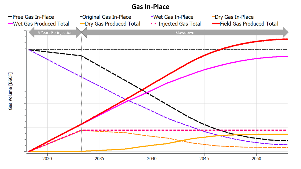
In this field simulation of just over 20 years, there is a five-year reinjection period followed by reservoir blowdown. Lean gas breakthrough does not really start until blowdown has commenced and by the end of field life a large proportion of the reinjected dry gas volume has been produced back. Although not shown in the plot, the reservoir pressure is maintained above dew point pressure throughout the recycling phase and only drops below dew point during reservoir blowdown.
Note that the total gas produced volume is greater than the original gas-in-place. This is because the gas produced includes both wet gas and dry gas, meaning that some gas molecules are produced more than once i.e. initially as part of a wet gas composition, and then again as part of a dry gas composition.
Note also the symmetry that can be seen in the produced volumes and gas-in-place. For the the injected gas, once lean gas breakthrough commences the total dry gas produced volume starts to approach that of the reinjected dry gas volume. In tandem the dry gas-in-place declines. This is because the injected dry gas volume minus the produced dry gas volume is equal to the remaining dry gas-in-place. Similarly the wet gas-in-place and the wet gas produced total volume mirror each other. In this case the original wet gas volume minus the produced wet gas volume is equal to the remaining wet gas-in-place and the ratio of total wet gas produced to the original wet gas-in-place is one measure of the gas recovery factor. Note that there are other ways of measuring the gas recovery factor. For example we could take the original dry gas-in-place volume and compare this to the total production of dry gas minus injected dry gas e.g., the total dry gas that is exported or sold. This could be higher than the wet gas recovery factor because later in field life some of the dry gas exported or sold was actually re-produced injected gas.
Application of Modified Black Oil Model
According to the OPM Flow manual the use of a modified black oil model is appropriate for modelling of gas-condensate recycling:
“The scope and accuracy of gas condensate modeling using black-oil reservoir simulators is well established in the industry; both depletion and gas cycling above the dew point can be modeled and yield an adequate match with the results from multi-component compositional simulators.”
How should a black oil model be used to model gas-condensate recycling? The simplest approach perhaps is to use a gas tracer. The tracer is associated with the injected gas volumes, and by examination of the concentration of produced tracer, the ratio of produced wet to dry gas can easily be determined. Unfortunately, whilst OPM Flow has implemented the use of tracers, it is not possible to use these with a modified black oil model (that is to say one containing both wet gas and live oil). Thus an alternative approach is required.
The PVT properties of the wet gas are defined, and the ratio of vaporised oil to gas is a function of the reservoir pressure. Above the dew point this is a constant value and this declines below the dew point as some of the vaporised oil condenses out into the oil phase. Similarly the PVT properties of the dry gas known, and there is zero vaporised oil associated with the injected dry gas. Since the vaporised oil to gas ratio (Rv) for wet gas is defined by known PVT properties, and the Rv for dry gas is zero, it is possible to ascertain the ratio of wet gas to dry gas within the reservoir from examination of the vaporised oil to gas ratio.
Let’s first consider the material balance for the known and unknown quantities of gas. These volumes can be classified as in-place, produced or injected volumes, for both wet and dry gas components.
| Variable Name | Description |
|---|---|
| FUOGASIP | Field original gas-in-place. This is 100% wet gas at the start of production. If there is no reinjection of dry gas, then the remaining wet gas-in-place plus the total produced wet gas volume will always equal the field original gas in place. |
| FU_WGIP | Field wet gas-in-place. The remaining and unproduced wet gas-in-place within the reservoir. |
| FU_WGPT | Field wet gas produced total. The total volume of wet gas produced. Note that FU_WGPT = FUOGASIP - FU_WGIP. |
| FGIT | Field gas injected total. The total volume of dry gas injected back into the reservoir. This volume can be determined from the amount of wet gas that has been produced as after liquids have been removed from the wet gas, the volume will shrink in a predictable manner. |
| FU_DGPT | Field dry gas produced total. Once lean gas breakthrough occurs, part of the reinjected dry gas will be produced. |
| FU_DGIP | Field dry gas-in-place. The balance of the reinjected dry gas that has not been produced back is, by definition, in-place within the reservoir. Thus FU_DGIP = FGIT - FU_DGPT. |
| FGIPG | Field gas-in-place for gas component. This is the total gas-in-place for the reservoir including both wet and dry gas. Note that it would technically be more correct to use FGIP which includes both the gas and oil components in the modified black oil model e.g. free gas and solution gas. Testing with OPM Flow led to errors using the FGIP variable, so as a compromise the FGIPG variable which is the free gas-in-place only was used. |
| FU_IPGPT | Field in-place gas produced total. Includes both wet and dry gas. This is the total amount of gas component that is produced, irrespective of whether the gas is associated with wet gas (Rv > 0.0) or dry gas (Rv = 0.0). Note that the calculation based on the addition of wet and dry gas produced totals is more accurate than the summary variable FGPT “Field gas produced total” . |
The volumetric relationships between these quantities is shown in Figure 2. The figure illustrates the relative volume for a given category of gas on a horizontal scale. The breakdown of a particular component into sub-components is shown using the same horizontal scale. Note that these volumes are for the gas component at standard conditions. Colour coding for the components is the same as used in the line plots for Figure 1 in order to aid comparison between the two figures.
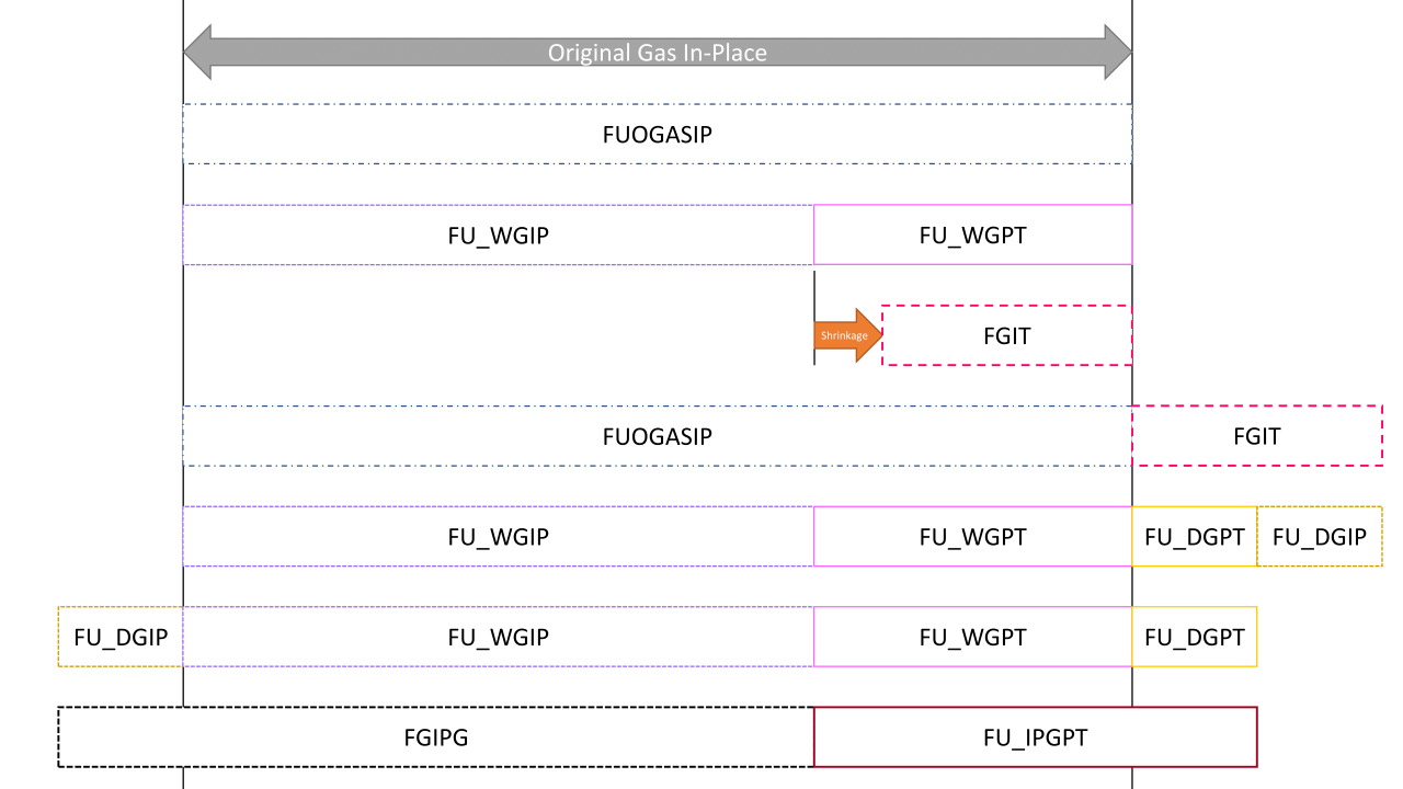
Working down the illustration, we start at the top with the field’s original gas-in-place (FUOGASIP). This quantity is known and defined by the static model used for the simulation. As previously noted, in the absence of any reinjection, the original gas-in-place is simply the total of the remaining wet gas-in-place and the total produced wet gas.
The situation is complicated by reinjection of dry gas. The reinjected dry gas volume is effectively determined from the total produced wet gas volume through consideration of the shrinkage factor. This factor can be calculated from the gas composition and the efficiency of the gas plant liquids extraction. Note that the reinjected dry gas volume can also contain lean gas breakthrough volumes. This is not shown in the illustration, but it does not affect the derived relationships.
Let us now consider as a whole the sum of two volumes: (1) the original field gas-in-place, and (2) the total reinjected dry gas volume.
- As previously stated the field original gas-in-place is the summation of the remaining field wet gas-in-place plus the field wet gas produced total. FUOGASIP = FU_WGIP + FU_WGPT.
- The injected dry gas volume must balance the remaining dry gas-in-place and the field dry gas produced total. FGIT = FU_DGIP + FU_DGPT.
Another way to relate these quantities to each other is via the field gas-in-place and the field gas produced total, both of which comprise both wet and dry gas. Therefore FGIPG = FU_WGIP + FU_DGIP and FGPT = FU_WGPT + FU_DGPT.
Several of these values are known/defined or can be obtained from the reservoir simulator. What is not known is the ratio of wet to dry gas. If one of these volumes can be defined, then through the relationships just described, it is possible to determine all other volumes.
Since only dry gas is injected, the Rv for wet gas in the reservoir matches the PVT tables that are input to the simulator. This value can be calculated using an equation that is obtained from correlation of the tabular PVTG values. It can also be expressed using the ratio of the field vaporised oil-in-place for the gas phase (e.g. condensate in the wet gas that has not yet dropped out) to the volume of wet gas-in-place. FU_RVPVT = FOIPG / FU_WGIP.
Re-arranging gives: FU_WGIP = FOIPG / FU_RVPVT. FOIPG can be obtained from the simulator and FU_RVPVT is the known Rv for the gas at a specific reservoir pressure. This means that it is possible to determine the wet gas-in-place precisely and from this all other wet and dry gas volumes are derived.
Furthermore, the field gas produced total (FGPT) is appears higher than the real volume of gas produced. An additional variable for the in-place gas produced total, FU_IPGPT = FU_WGPT + FU_DGPT, was introduced to ensure all values reconcile. Note that FU_IPGPT != FGPT.
Correlating PVTG Below Dew Point
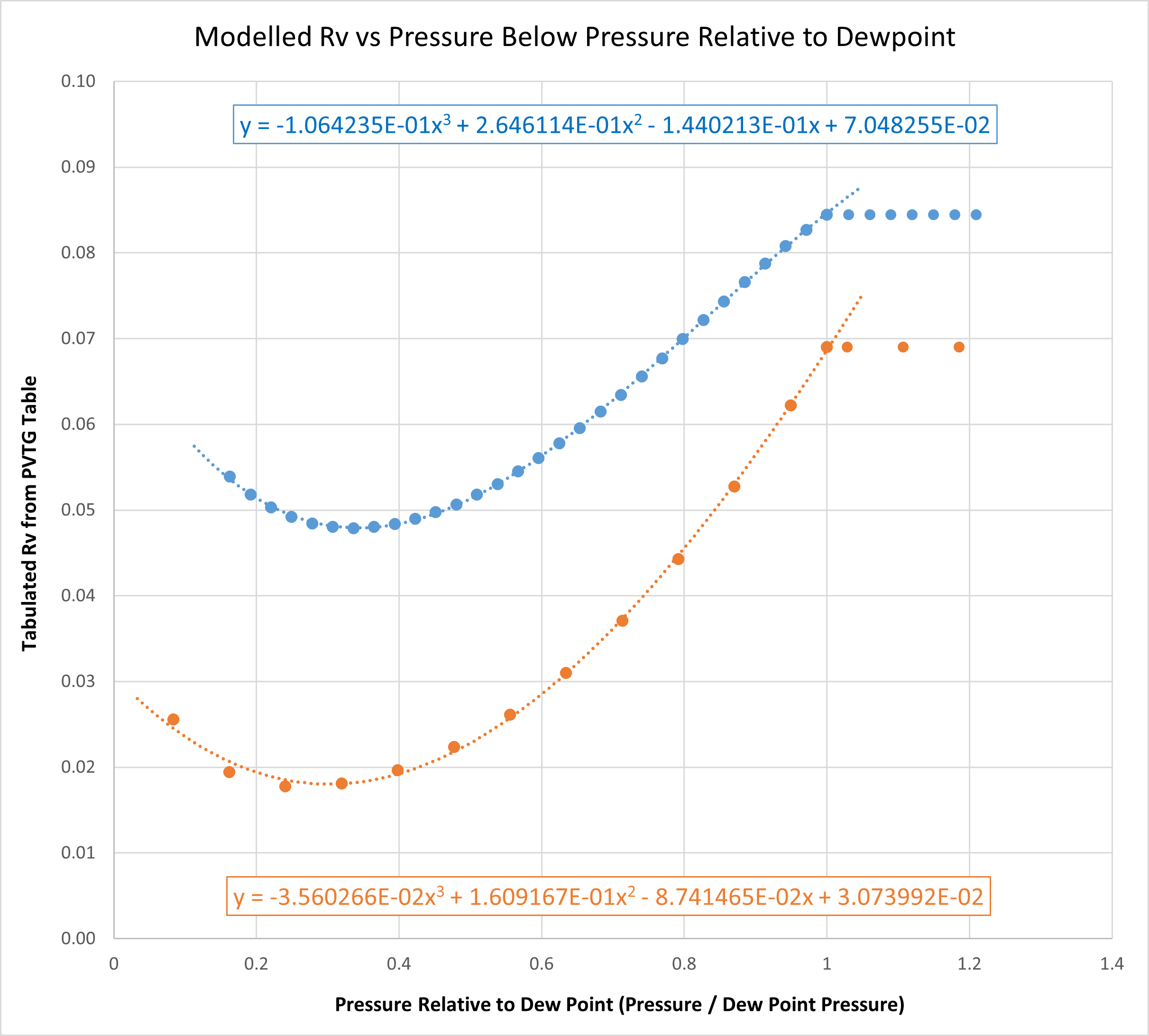
For the FU_RVPVT variable to be properly defined, it is necessary to derive a relationship between the reservoir pressure and the vaporised oil-gas ratio. Above dew point pressure this is a constant value. Below dew point pressure this will vary and the simulator will look up the value using a pre-computed lookup table which is usually input using the PVTG keyword. Unfortunately there is no way to access a lookup value from this table within a user defined quantity, and an alternative approach is required to obtain the Rv for wet gas at a known pressure.
The approach taken is to use correlation to obtain an equation that describes the behaviour of the variation in Rv below the dewpoint. The correlations are improved if the pressures are first normalised to the dew point pressure. This is achieved simply by dividing by the dew point pressure. By correlating only points below the dew point, it is usually possible to fit a polynomial equation that describes the behaviour. An example using two different PVT laboratory measurements for a gas-condensate is shown in Figure 3.
OPM Flow Keywords
To model the proportion of wet and dry gas produced and remaining within the reservoir, several user defined quantities are required. The following script used within the SCHEDULE section will allow tracking of gas-condensate recycling. Note that the custom UDQ variables (those starting with ‘FU’) also need to be added to the SUMMARY section otherwise they will not be output and interrogation of the results is not possible.
Note that the correlated polynomial equation cannot be entered on a single line in OPM Flow as this violates the maximum number of characters permitted for a user defined quantity. The workaround, shown here, is to break the polynomial up into several parts and then combine those to calculate the final Rv.
Because our FU_RVPVT varible comprises two parts, one value if above dew point pressure and another if below, a trick is used with a flag variable. This flag variable (FUFLAGDP) is set to either 0.0 (above dew point) or 1.0 (below dew point). The final FU_RVPVT value is built from both the values, but through the flag only the appropriate value is applied. The flag is set using an ACTIONX keyword that checks for when the field pressure (FPR) falls below the dew point pressure (FUDEWPRS – defined in the UDQ keyword).
In addition to calculating the total volumes and rates for the various wet and dry gas quantities as shown in Figure 2, the following snippet contains user defined quantities for calculation of related yields and recovery factors. These are provided without further explanation, although it is hoped they should be self-explanatory. The script below has been modified to account for an improved method of calculating the wet gas and dry gas quanitities from Rv.
--
-- ********************************************************************************
--                             USER DEFINED QUANTITIES
-- ********************************************************************************
--
-- ------------------------------- DEFINE VARIABLES -------------------------------
UDQ
   ASSIGN FUDEWPRS 3073.831                                                        / Dewpoint Pressure for Wet Gas (psia)
   ASSIGN FURV     0.08446                                                         / PVT Sample Oil-Gas Ratio (stb per Mscf)
   ASSIGN FUNGLYLD 0.08294                                                         / Condensate Gas Plant Yield (stb per Mscf)
   ASSIGN FULPGYLD 0.07251                                                         / LPG Gas Plant Yield (stb per Mscf)
   ASSIGN FUTOTSHK 0.2319                                                          / Total Shrinkage Including Process Loss and Fuel Gas
   ASSIGN FUDELTA  1.0E-10                                                         / Value to Avoid Divide by Zero Errors
   ASSIGN FUFLAGGS 0.0                                                             / Gas Sales Logical Flag
   ASSIGN FUFLAGDP 0.0                                                             / Below Dew Point Logical Flag
   DEFINE FURELDPP FPR / FUDEWPRS                                                  / Field Pressure Relative to Dewpoint Pressure
   UNITS  FURELDPP 'PSIA/DEWPOINT'                                                 /
   DEFINE FU_RVA   -1.064235E-01 * FURELDPP * FURELDPP * FURELDPP                  / FU_RVPVT Polynomial Equation Part A
   DEFINE FU_RVB   2.646114E-01 * FURELDPP * FURELDPP                              / FU_RVPVT Polynomial Equation Part B
   DEFINE FU_RVC   1.440213E-01 * FURELDPP                                         / FU_RVPVT Polynomial Equation Part C
   DEFINE FU_RVD   FU_RVA + FU_RVB - FU_RVC + 7.048255E-02                         / FU_RVPVT Polynomial Equation Part D
   DEFINE FU_RVPVT FU_RVD * FUFLAGDP + FURV * (1 - FUFLAGDP)                       / Actual Wet Gas Oil-Gas Ratio (stb per Mscf)
   UNITS  FU_RVPVT 'STB/MSCF'                                                      /
   DEFINE FUOGASIP FGIPG + FGPT - FGIT                                             / Original Field Gas In-Place
   UNITS  FUOGASIP 'MSCF'                                                          /
   DEFINE FUONGLIP FUOGASIP * FUNGLYLD                                             / Original Condensate In-Place
   UNITS  FUONGLIP 'STB'                                                           /
   DEFINE FUOLPGIP FUOGASIP * FULPGYLD                                             / Original LPG In-Place
   UNITS  FUOLPGIP 'BBL'                                                           /
   DEFINE FU_WGPR  FOPRS / FU_RVPVT                                                / Wet Gas Production Rate
   UNITS  FU_WGPR  'MSCF/DAY'                                                      /
   DEFINE FU_DGPR  FGPR - FU_WGPR                                                  / Dry Gas Production Rate
   UNITS  FU_DGPR  'MSCF/DAY'                                                      /
   DEFINE FU_DGPTS FU_DGPR * TIMESTEP                                              / Dry Gas Produced Total (total for timestep from rate)
   UNITS  FU_DGPTS 'MSCF'                                                          /
   ASSIGN FU_DGPT  0.0                                                             / Dry Gas Produced Total
   DEFINE FU_DGPT  FU_DGPT + FU_DGPTS                                              /
   UNITS  FU_DGPT  'MSCF'                                                          /
   DEFINE FU_DGIP  FGIT - FU_DGPT                                                  / Field Dry Gas In-Place
   UNITS  FU_DGIP  'MSCF'                                                          /
   DEFINE FU_WGIP  FGIPG - FU_DGIP                                                 / Field Wet Gas In-Place
   UNITS  FU_WGIP  'MSCF'                                                          /
   DEFINE FU_WGPT  FUOGASIP - FU_WGIP                                              / Wet Gas Produced Total
   UNITS  FU_WGPT  'MSCF'                                                          /
   DEFINE FU_IPGPT FU_WGPT + FU_DGPT                                               / In-Place Gas Produced Total
   UNITS  FU_IPGPT 'MSCF'                                                          /
   DEFINE FU_OGR   1.0 / FGOR                                                      / Current Producing Oil-Gas Ratio
   UNITS  FU_OGR   'STB/MSCF'                                                      /
   DEFINE FU_NGLR  FOPR * (FUNGLYLD / FURV)                                        / Condensate Production Rate
   UNITS  FU_NGLR  'STB/DAY'                                                       /
   DEFINE FU_NGLRC FU_WGPR * FUNGLYLD                                              / Condensate Production Rate (Check)
   UNITS  FU_NGLRC 'STB/DAY'                                                       /
   DEFINE FU_NGLT  FOPT * (FUNGLYLD / FURV)                                        / Condensate Produced Total
   UNITS  FU_NGLT  'STB'                                                           /
   DEFINE FU_NGLY  FU_NGLR / (FGPR + FUDELTA)                                      / Producing Condensate Yield
   UNITS  FU_NGLY  'STB/MSCF'                                                      /
   DEFINE FU_LPGR  FU_WGPR * FULPGYLD                                              / LPG Production Rate
   UNITS  FU_LPGR  'BBL/DAY'                                                       /
   DEFINE FU_LPGT  FU_WGPT * FULPGYLD                                              / LPG Produced Total
   UNITS  FU_LPGT  'BBL'                                                           /
   DEFINE FU_LPGY  FU_LPGR / (FGPR + FUDELTA)                                      / Producing LPG Yield
   UNITS  FU_LPGY  'BBL/MSCF'                                                      /
   DEFINE FU_NGPR  FGPR - (FU_WGPR * FUTOTSHK)                                     / Post-Processing Net Gas Production Rate
   UNITS  FU_NGPR  'MSCF/DAY'                                                      /
   DEFINE FU_SGPR  FU_NGPR * FUFLAGGS                                              / Sales Gas Production Rate
   UNITS  FU_SGPR  'MSCF/DAY'                                                      /
   DEFINE FU_GIR   FU_NGPR * (1 - FUFLAGGS)                                        / Gas Re-Injection Rate
   UNITS  FU_GIR   'MSCF/DAY'                                                      /
   DEFINE FU_NGPT  FU_IPGPT - (FU_WGPT * FUTOTSHK)                                 / Post-Processing Net Gas Produced Total
   UNITS  FU_NGPT  'MSCF'                                                          /
   DEFINE FU_SGPT  (FU_NGPT - FGIT) * FUFLAGGS                                     / Gas Sales Produced Total
   UNITS  FU_SGPT  'MSCF'                                                          /
   DEFINE FU_GASRF (1.0 - (FGIPG / FUOGASIP)) * 100.0                              / Gas Recovery Factor
   UNITS  FU_GASRF '%'                                                             /
   DEFINE FU_WGRF  (FU_WGPT / FUOGASIP) * 100.0                                    / Wet Gas Recovery Factor
   UNITS  FU_WGRF  '%'                                                             /
   DEFINE FU_SGRF  (FU_SGPT / (FUOGASIP * (1.0 - FUTOTSHK))) * 100.0               / Sales Gas Recovery Factor
   UNITS  FU_SGRF  '%'                                                             /
   DEFINE FU_NGLRF (FU_NGLT / FUONGLIP) * 100.0                                    / Condensate Recovery Factor
   UNITS  FU_NGLRF '%'                                                             /
   DEFINE FU_LPGRF (FU_LPGT / FUOLPGIP) * 100.0                                    / LPG Recovery Factor
   UNITS  FU_LPGRF '%'                                                             /
/ End of UDQ Keyword
--
-- ------------------------- DEFINE GLOBAL CUSTOM ACTIONS -------------------------
--
-- Calculate the gas re-ininjection rate for the group after stripping liquids
-- (condensate and LPG) from the produced wet gas.
ACTIONX
    GRUPINJ    10000  30.4375          /
                 FGIR   > 0            /
/
--
-- --------------------------- GROUP INJECTION CONTROLS ---------------------------
--
--     GRPNAME       TYPE     TARGET       RATE       RESV       REIN       VREP    GRPCNTL
--  ---------- ---------- ---------- ---------- ---------- ---------- ---------- ----------
GCONINJE
       'FIELD'      'GAS'     'RATE'     FU_GIR         1*         1*         1*         1* /
/
ENDACTIO
--
-- Flag when pressure drops below dewpoint.
ACTIONX
   SETFLGDP        1                   /
                  FPR  <= FUDEWPRS     /
/
UDQ
   DEFINE FUFLAGDP 1.0                                                             / Logical flag for below dew point
/ End of UDQ Keyword
ENDACTIO
--
-- Turn off updates to original gas in place UDQ.
ACTIONX
   LOCKOGIP        1                   /
                 FGPT   > 0.0          /
/
UDQ
   UPDATE FUOGASIP OFF                                                             /
   UPDATE FUONGLIP OFF                                                             /
   UPDATE FUOLPGIP OFF                                                             /
/ End of UDQ Keyword
ENDACTIO
Quasi-Compositional Model using OPM Flow
As a final thought, an option exists in the OPM Flow simulator to vary the PVT properties for PVTO and PVTG depending on the concentration of fourth phase: a solvent. The logic is compelling. If the dry gas composition is fixed, and the original reservoir wet gas composition is known, then the properties for the mixed reservoir gas are purely a function of the fraction of injected dry gas and original wet gas.
The functionality is enabled using the PVTSOL keyword which essentially allows several PVTO and PVTG tables to be defined at different solvent concentrations between 0.0 and 1.0. I haven’t explored this option yet. It appears to be a worthwhile exercise as it would overcome most shortcomings that arise from not having a compositional simulator whilst still allowing the faster and simpler modified black oil formulation to be utilised.