About a month ago the family and were finally able to move into our “forever” home. This is a house that was built by a project home builder, G.J. Gardner (Springfield) according to our own modifications. An earlier blog post showed an early idea for the house which was rendered using Blender. Personally I would argue that the modifications stayed true to the original design. Others have pointed out that the addition of a second storey can hardly be considered a minor modification. Since it is about two years since I wrote the original post, an update on how the project turned out seems appropriate.
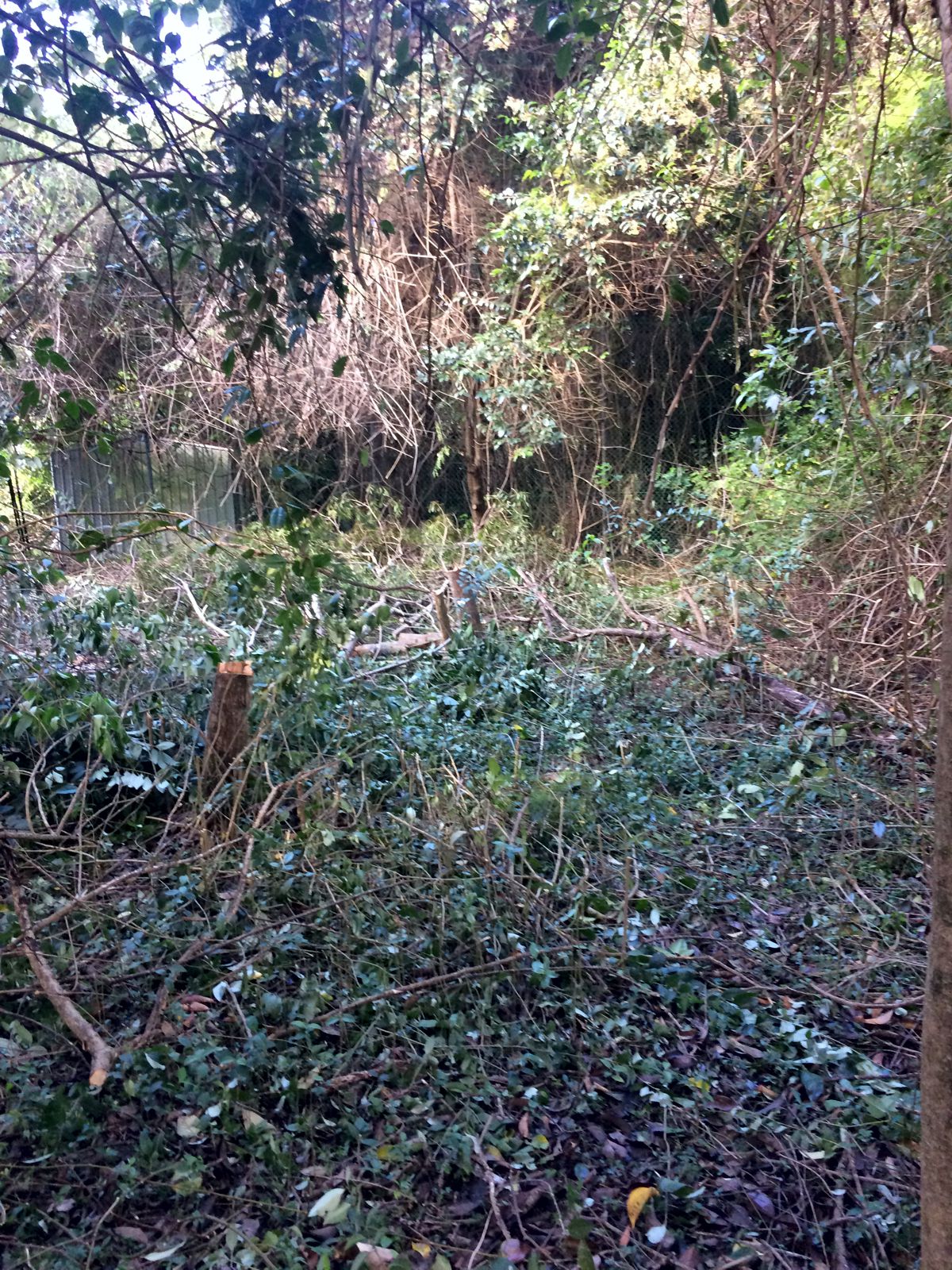
After looking at several potential sites, in November 2018 we found an ideal location on Tamborine Mountain and in early 2019 we took the plunge and acquired the land for our future home. The land we had purchased is located on a gently sloping plot that faces due north with views over the tops of the trees on the mountain. Initially the land was covered with avocado trees from its former use as an orchard, and there was an abandoned and overgrown tennis court in one corner. Other than the land itself, there was very little else. Power, water, sewage, internet, driveway access, even the address itself, would need to be considered and provided for. Overall it had a lot of potential that had to be imagined as, truth be told, there wasn’t a lot to see.
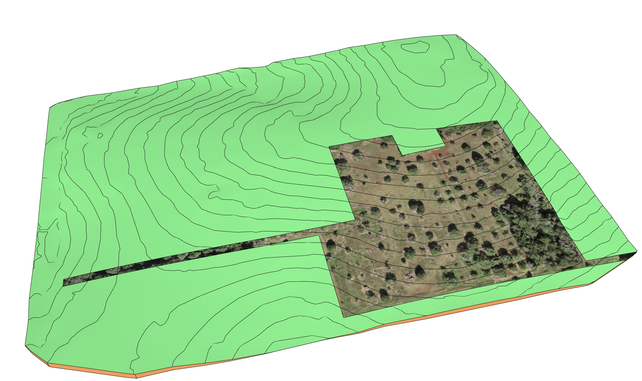
A big tip of my hat to my father-in-law who set to work on getting the land into a state where it could be built on. When we first acquired the land it was covered in avocado trees, having previously been an orchard. Access to the property was non-existant and a new driveway needed to be constructed down to the main road. This led to the purchase of a tractor which was somewhat smaller than Jeremy Clarkson’s Lamborghini. Yes - tractor envy really is a thing even though my father-in-law tells me that looks can be deceiving and that this little Kioti packs a real punch.


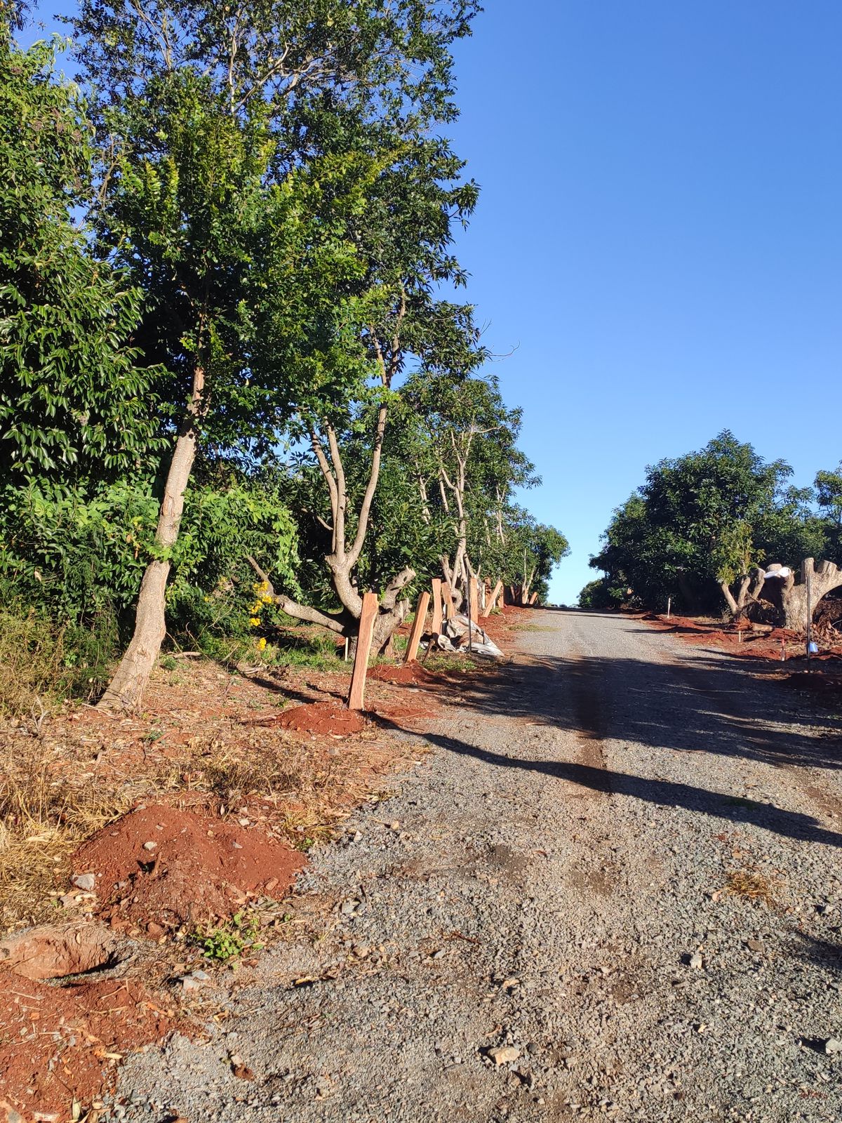

By the end of 2019 the land had been cleared of trees, a bore was drilled to access water and electricity to the property had been arranged. Mind you, this wasn’t without its share of dramas. Having been advised by a water diviner of the ideal location, perhaps it was inevitable that because I work in the oil and gas industry, the first well was a dry hole. We kept drilling to over 100 metres but didn’t encounter any permeable formations. Eventually we redrilled in a location near to where one of our neighbours has good well and hit a productive aquifer. We should have just started there!
With access to a mostly cleared parcel of land, and the necessary utilities we were ready to build. In the meantime, whilst the land was being cleared, work on bringing life to the home design was continuing in the background so that we would be ready to get started with the build as soon as the land was ready. At least that was the plan…
Using SketchUp to Experiment with Changes
The advantage of a 3D model is that you can make changes and if you don’t like them, then you can simply undo them or adjust them slightly. In theory it is easier to change electrons than it is to change brick and steel once you’ve built it.
What we hadn’t anticipated was that the ability to visualise changes would lead to a endless series of arguments between my wife and I as we debated every little nook and cranny, colours, room sizing etc. Of course it was beneficial to get this all out of the way before the build started. In the end we had very few changes on the house – the most major one being the addition of a downlight in a corridor where I had missed it off the plans.
As a result of these discussions the house continued to evolve between the initial adaptation of the Montville 462 design in August 2018, through to changes made to the model during construction to help with decisions that needed to be made. A comparison of how the model evolved can be seen in the following snapshots:
The application of the model to understand the changes also continued to evolve throughout the project as we began to understand how best to use the software.
- August 2018 - Initial Adaptation: The changes to the base Montville 462 design were straightforward. The primary objective was to translate the 2D layout plan into a 3D model and to investigate whether the addition of a second storey would be practical. This meant that the second storey would need to fit onto the existing ground floor without causing any obvious structural issues and that the adapted house would also look reasonable. During this iteration of the model a lot of effort was invested in learning how best to use the software. At this stage I wasn’t using layers extensively and textures were only rarely used. The x-ray perspective view was used to see through walls and to help see how the building fit together. The main changes made at this stage were:
- The addition of a second story meant that the central part of the house was widened in order to accommodate a staircase in the atrium. This marginally increases the floor area on the ground floor.
- Changing the layout of the kitchen to steal space from the original master bedroom walk-in wardrobe. This simply reconfigures some internal walls and is not a dramatic change.
- The the garage was reduced from three cars to two plus a carport. The cost saving is marginal as the slab area and roofing are effectively unchanged.
- The original master bedroom ensuite was shrunk in order to introduce a storeroom off the laundry. Overall this led to a small increase in gross floor area and is again a minor reconfiguration of internal wall layout.
- January 2019 - Proposed Attached Accomodation: Following the initial iteration of the model, a number of conversations were sparked concerning the layout and practicality of the house. Often my wife would insist that a change be made and I would naturally resist, being so proud of my 3D baby I didn’t want to change it, only to find that the change was actually decent. By this stage modelling we were both getting more comfortable with SketchUp. By keeping the main file on Dropbox we were easily able to keep copies on our local machines in sync. The general rule was that my wife could open the file and muck around as much as she liked, provided she didn’t save over the base working copy.
- By this stage we had also discovered the 3D Warehouse which allows models created by others to be shared and downloaded into your own model. There are literally thousands of ready-made objects, including furniture, lighting and appliances. Browsing the different categories allowed us to experiment with interior decorating and seeing how the space worked (or didn’t) with different size furniture.
- I spent a huge amount of time researching acoustics for the home cinema and found it is a veritable rabbit warren of information. The 3D model even incorporates sound absorption panels and diffusers based on an open source design. More critically was the seating arrangement which necessitated moving some walls to ensure the seats could fit in the room. At this point it was clear that using SketchUp to test how the house would be used was extremely valuable.
- As my in-laws were going to be moving to our property to live, there were competing options of a separate detached “granny flat” or an attached seperate accomodation. We ran two models in parallel. (1) a separate detached house design and (2) an expanded main house. Again, a huge advantage realised through using 3D modelling.
- Changes were made to the kid’s wing to optimise the layout. Generally the layout appears identical but closer inspection shows that all the bedrooms have been marginally enlarged, and the bathroom has been enlarged along with the addition of a walk-in robe for one of the bedrooms. Essentially the modelling showed that the original design had pushed hard to compact as much into the space as possible. By relaxing the space constraint slightly it was possible to make the rooms just a little larger and thus feel larger when a double bed was placed in each.
- Some of the biggest arguments came from colour selections. My wife would love to pick out tiles and we were particularly interested in wood-look tiles. Of course this then led to many issues as where on earth was I going to find a texture to replicate the tile selection? Modelling is great, but if you can’t actually see what your material selections will look like, then it’s just a pretty gimmick. What I found was that using 2D imaging software to warp, crop and tessellate textures was invaluable. PixPlant and Materialize are two programs that I used and which saved a lot of heartache.
- We expanded the laundry into the garage space as we just couldn’t comprehend how such a narrow laundry was viable in the original plan. Now that the house is built, I can conclude that the original plan was probably just about servicable, but I’m glad we modified the design to make it larger.
- An unhealthy amount of time was spent designing stairs. For such a seemingly simple premise, the number of possible permutations combined with requirements to meet code etc. are staggering.
- Perhaps the biggest amount of time and effort was spent on the kitchen and butler’s pantry. My wife was adamant that we would have a kitchen using Blum products. Astonishingly Blum even has free software that allows you to design your cabinets and export them in 3D. This helped with many different kitchen configurations and eventually we settled on one particular layout. That said, there are many aspects to good kitchen design, and there were still a few changes to come before we commenced construction!
- April 2021 - Construction Modifications: By the time we signed the building contract the secondary accommodation annex had been dropped in favour of a separate detached house, and the second story had survived. At one point I had an attic up in the roof space but that was eliminated as an unnecessary expense. My ambitions for a wine cellar were unfortunately never realised as I could never figure out how to fit it into the design. With hindsight a more experienced architect would have designed the house to take adantage of the slope of the land, reducing the amount of earthworks required and probably creating an opportunity for a wine cellar and basement in the process. Overall the layout of the main part of the house remained quite stable with most effort put into colour selections etc. As we commencing building, understanding how certain aspects of the design were going to be implemented in detail meant that I could take as-built measurements and update the model accordingly. An example of when this was very useful was with the alfresco area where the interface between the balcony and verandah roof hadn’t been worked out in detail. By using the 3D model we were quickly able to model a few different configurations and send the pictures of the design to the builder. With regards to 3D modelling I had also discovered the beauty of architectural rendering. Tempted by the promise of photo-realistic rendering I acquired a licence for Twilight Renderer. My personal view is that this isn’t as good as the Cycles renderer in Blender, but it is a lot easier to set up and use from within SketchUp as it doesn’t require an export of the 3D model into another format.
Tips for Effective Use of SketchUp for Architecture
One of the strong qualities of SketchUp is that it is intuitive to grasp and thus quite easy to create your first 3D models. The problems come when your models start to become complex and there are many more objects to manage. At this point you start to learn a bit more and find out that things would have been so much easier if only you had started the model slightly differently. There are many guides for learning SketchUp and I certainly don’t plan to replicate them here. It does seem worthwhile sharing a few tips that I felt would have been most valuable to know when I started.
- Organise Your Model: Perhaps because it is not shown by default, it took me ages to realise there was a way to organise your model with nested objects/groups/components within each other. This allows a logical organisation of the model to be arranged e.g. at the highest level you have a house, within that a ground floor and a second floor, within each floor you have walls and rooms, and within each room you can place furniture, windows, doors etc. Note that the organiser should group objects by using a physical logic e.g. objects that are literally contained within each other.
- Shortcuts are Your Friend: In a 3D modelling program, having to move the mouse cursor to select a command means that your cursor is no longer in the vicinity of the object you are working with. This is inefficient and after a while it becomes tedious. The answer is to use keyboard shortcuts. Once you have mastered the basic ones, you’ll want to add your own to suit your workflow. Perhaps the most common ones I use in day-to-day work are ‘SPACE’ to active the selection tool, ‘P’ for push-pull tool, ‘M’ for a simple move and addition of ‘CTRL’ duplicates the selected object.
- Use the Inference Engine: As a beginner it is frustrating to try to align objects and create geometry that is perfect without minor wonkiness. My experience was that this was simply because I had no idea how the inference engine helps to intelligently ‘snap’ to other objects and geometry in 3D.
- Click-click Not Click-drag: Perhaps because of familiarity with how tools in other programs work, the natural way to try to draw or move something in SketchUp is to click and then drag. This can be difficult to achieve with any level of accuracy as precisely moving a mouse whilst holding down the left button is harder than just moving the mouse. SketchUp allows an alternative approach which is to click and then release (with the behaviour now mimicking a dragging action) and then click again to end the dragging action. This is less intuitive but after trying it a few times you’ll discover it is much more powerful. When combined with the use of arrow keys to lock the direction to a specific axis, the inference engine (and locking inferences using the ‘SHIFT’ key), or directly entering the amount to be used after clicking, it will be quickly found that there is very little benefit (if any) to the conventional click and drag action.
- Enter Measurements Directly: Want to make a cube that is 100 x 100 x 100? You could try click and drag to get a rectangle the right size, and then push-pull the face with another click and drag until you have formed a cube. Or … Select the rectangle tool, click where you want to cube to be located (possibly using inference to make sure it is exactly where you need it), type ‘100, 100’ and hit ‘ENTER’. Then ‘SPACE’ for selection, ‘P’ for push-pull, click to select the rectangle face you just drew, type ‘100’ and hit ‘ENTER’. Voila - a perfect cube. Note that if you do click and drag or create an object and want to change its dimensions you won’t even need to select the object. Just type a number and hit ‘ENTER’ and the last move or draw you did will be redone with the new dimension.
- Different Selection Methods: The selection behaviour when clicking and dragging from left to right is different to when clicking and dragging from right to left. This is easily overlooked but once you know about it you’ll find it is a very powerful technique.
- Learn to Love Components: Models often have many duplicated elements. In a house the windows and doors are prime examples of such duplicated objects. Unlike a group, a component is a copy of the original, and changes to that component are reflected across all other similar components. Therefore updating and maintaining the model is far easier when components have been used sensibly throughout. Generally components should be used where there is a discrete object, even if there is only one instance. For example a chair should be a component, but it’s legs, seat, back and cushions might be better implemented as groups.
- Search for and Use Existing Models: There are many different sources of free 3D models available. The 3D warehouse built into SketchUp is perhaps the most accessible and contains several vendors that have created models for their products so that these can be used immediately in SketchUp. This allows an interior to be quickly populated and the flow of the room to be visualised. My wife is still trying to come to terms with the fact that one of the reasons we have Fisher & Paykel appliances in our house is not just because they are quite good, but also because 3D models that could be imported into SketchUp were available!
- Group Separated Geometry: Grouping is a very important technique in SketchUp. Normally SketchUp assumes that your are editing the same geometry, so if you add additional points, they will become part of that object. This allows edges and faces to be stuck to each other easily, and can be very helpful when patching over holes. For beginners that aren’t aware that without groups their model is one single giant object, it can lead to frustrating problems when you try to move a wall and find that it is stuck to the floor which therefore decides to warp itself when the wall is moved.
Creating Concept Drawings
The professional version of SketchUp has a utility program called LayOut. This program allows you to take a 3D model and create 2D drawings directly from the model. If everything is set up correctly, then as changes are made to the 3D model, they are simultaneously reflected in the 2D drawings. This means that effort can be focused on working on the house design in 3D, and the 2D drawings are then just supporting documentation that is seamlessly and easily created directly from the 3D model.
Builders are used to working with 2D drawings and do not regularly use 3D software. Creating a set of plans and elevations that match the 3D model exactly will improve communication with the builder. Without the 2D drawings we would very likely have had a very difficult time explaining the changes to the layout that we wanted to make to the house.
Having said that a ‘proper’ set of 2D drawings will still need to be generated by the builder or their draftsman. One of the surprises that I ran into was when I came to review the offical drawings that were to be submitted for planning. I had provided our 3D model and a set of 2D drawings to the builder, thinking that this would be helpful. What I think then happened was that the PDFs of the 2D drawings were sent out to be re-drafted properly, but the 3D model was not sent to the draftman. This led to some areas where it was difficult to interpret exactly what was on the 2D drawings I had created. Eventually I ended up on the phone with the draftsman and asked, “why don’t you just look on the 3D model so you can see exactly what it’s meant to look like” and he replied, “what 3D model?” In a few minutes I had sent him the SketchUp model via the cloud and he was able to open it whilst we were still on the phone. His statement that, “this job would have been so much easier if I had just started with this” was astonishing because whilst both of us understood that the model was very useful, in hindsight that may not have been as apparent to our builder.
Rendering
The icing on the cake once you have a 3D model is rendering. This is the process of turning a 3D model into a photo-realistic picture. The most sophisticated approaches use ray-tracing to map how light interacts with surfaces to create believable images. It is a technique commonly used by the film industry to create artificial worlds. An earlier attempt at rendering used the Cycles rendering engine in Blender, but as this requires an export into another program, it was felt that a simpler approach might be preferable.
I used the Twilight Renderer for SketchUp which did not create results that were as good as Cycles, but were certainly passable. One of the main attractions is that because it can run directly from within SketchUp, and the model can be geolocated precisely, it is possible to match the sun position at any time of day throughout the year. This makes it very useful to see how sunlight will penetrate into a room (or not).
With the renders of the house completed, the “vision” of our house was now ready. More than just 2D drawings we could actually see what we were planning to build. So how did it turn out?
Results
The comparison of “vision to reality” is shown below. There are two scenes: an interior and exterior render. Both renders are completed using a model that was made before the build commenced and an attempt has been made to use a photograph from exactly the same position once the build was mostly complete as a comparison. I’ll admit it was quite hard to do with the exterior render, so in the end I found it was actually easier to move the virtual camera to the position where the real-life photo was taken and then re-render the scene.
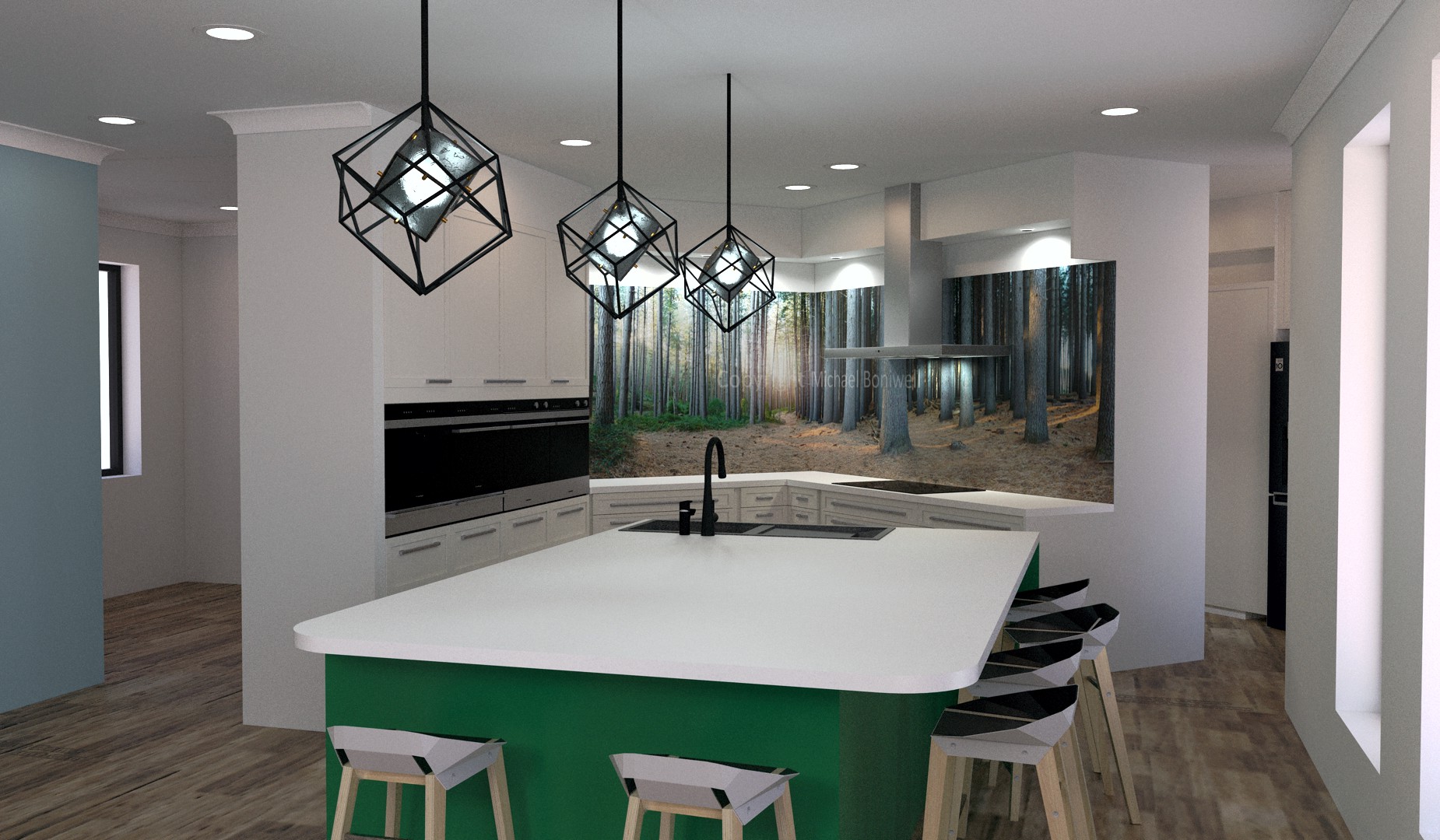

The kitchen comparison shows that the final build turned out quite similar to the planned model. There are a few changes here and there in the details, but overall the actual build was very close to what was originally proposed in the conceptual model. Certainly the feel of the kitchen and its layout are identical.
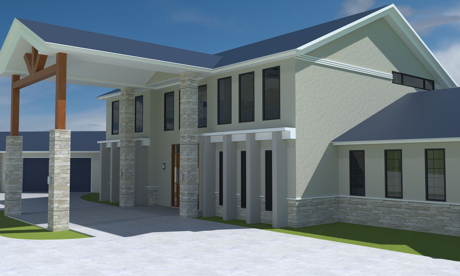
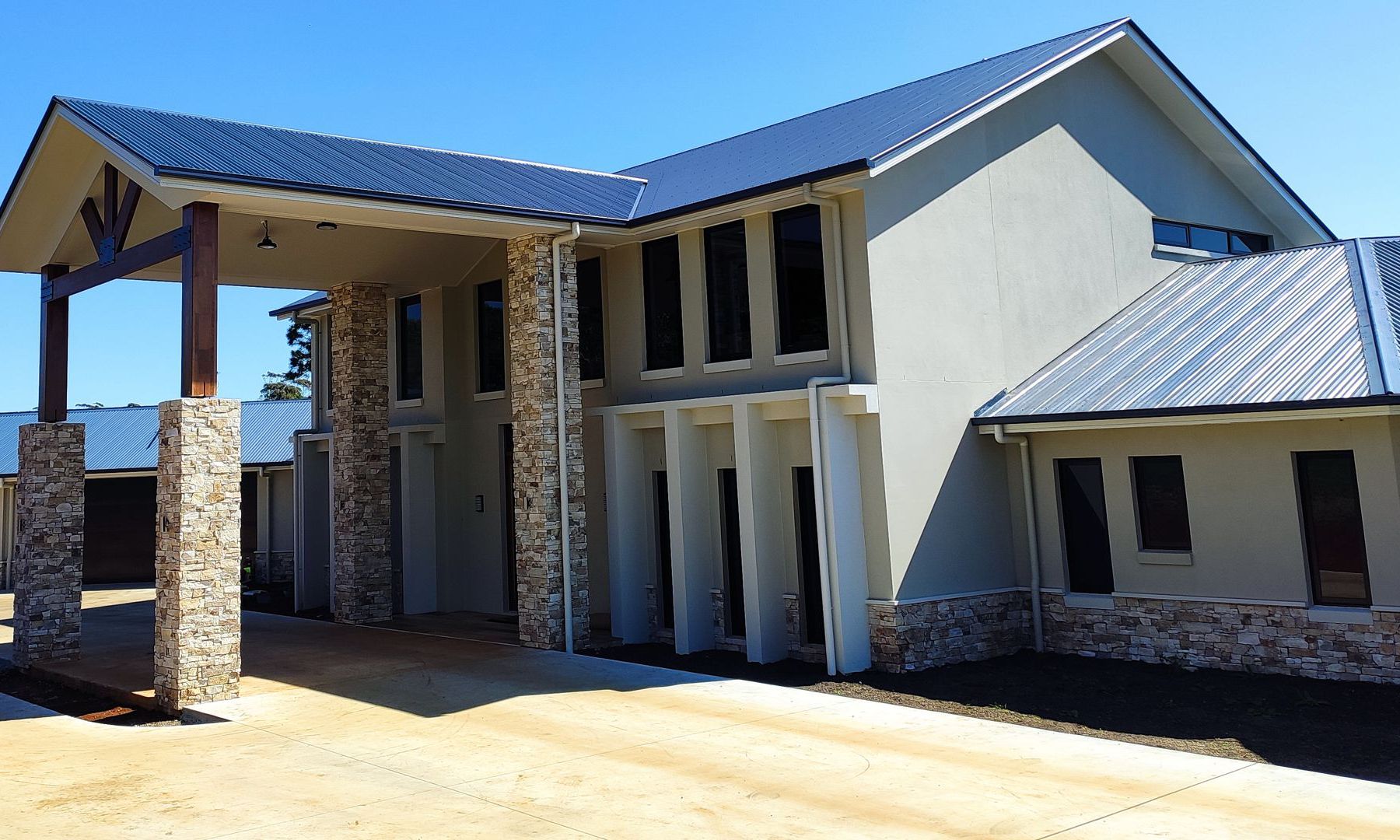
The exterior comparison also shows a good match. In the comparison render I have actually set the time of day to match when the photo was taken, and even the shadows cast by the building match really well. Again, other than some small changes to window layouts in one of the rooms, the rendered ‘vision’ matches the ‘reality’ very well.
Overall we feel that the effort put into the front-end of the project, in taking the time to prepare and specify the details of the house carefully, has paid off and helped ensure that final build matches the expectations closely. There were very few changes along the way – perhaps because all the arguments and changes had already happened in during the virtual build of the 3D model? In thies vein, the use of visualisation tools to help communicate with the builder was worthwhile, but in retrospect there was more value for us as owners to help envision what was being designed. We were able to test different colour schemes, test the addition or removal of windows, resizing rooms (even adding an attached separate living space at one point), check how different appliances and furniture would fit into the space etc.
The truth is that the builder is quite capable of building using 2D drawings alone. However the builder isn’t the one that will live there. That is what the owner will do, and it is the owner than needs to see how everything fits together before it is built, to check that this is really what is wanted. Because we took the time to create the vision, the reality has turned out well. Without that step, I know for certain that the vision in my head wouldn’t have matched the vision in my wife’s head, and the reality would probably have been somewhat disappointing as a result.
After the build was completed a colleague asked me, “now that you’ve completed the build, have you found things that you would have done differently?” To be honest, I struggled to answer. Most of the build turned out just as we had envisioned. That is, I believe, a good outcome.