Over the past several decades, SEG‑Y has become the de‑facto standard for storing and exchanging seismic data. Perhaps because it started out as a magnetic tape format in an era when ASCII and IEEE floating point numbers had not even been defined, and has survived the transition to spinning hard drives and now solid state drives, real-world SEG‑Y files can be surprisingly inconsistent for what is supposedly a well defined standard. In the wild, files often contain inconsistencies, non‑standard header locations, mixed endian issues, or incomplete geometry. Before importing a SEG‑Y file into a Pyrus project, it is strongly recommended to inspect the file to ensure that the header information and geometry are correct.
The SEG‑Y Inspector Tool in the Pyrus Suite provides a fast, interactive way to examine textual headers, binary headers, trace headers, geometry, and preview of seismic lines. This article explains how to launch the tool, how to interpret the information it displays, and how to make small corrections to header byte locations when necessary.
Launching the SEG‑Y Inspector Tool
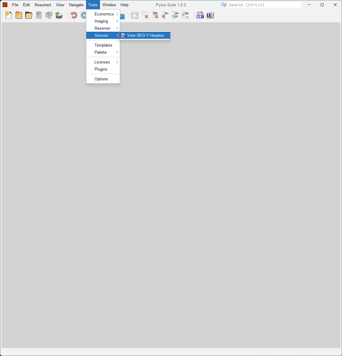
The SEG‑Y Inspector can be launched from the main Pyrus application window using:
Tools > Seismic > SEG‑Y Inspector
This opens a dedicated inspection panel within the Pyrus environment. Multiple panels can be opened for different files, although in practice just a single window is required.
When a file is selected, Pyrus opens it using a memory-mapped reader using Java. This supports fast random access to traces and headers, even for very large files. Despite this, it must be remembered that SEG-Y is an older format, and for very large files, expecting miraculous speed reading certain data – for example z-slices – is unreasonable. For this reason the SEG-Y inspection tool is limited to previewing traces, inlines and crosslines only.
Textual Header (EBCDIC / ASCII)
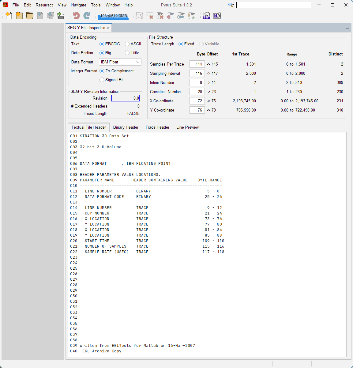
Every SEG‑Y file begins with a 3,200 byte textual header. The inspection tool converts the textual header bytes into to readable text, and displays it in a structured 40-line format. By default Pyrus will open this using the original EBCDIC character encoding. This is a much older character encoding system that pre-dates the more common ASCII character encoding. Many SEG-Y files tend to correctly observe this specification, although there are occasional files that use ASCII instead. Pyrus allows the character encoding to be switched between these two character encoding systems. It should be easy to determine which is correct as the text will appear garbled when the incorrect encoding is used.
The main purpose of the textual header is purely informational. Because it is freely structured, the contents and layout of this file will vary enormously from one SEG-Y file to another. For this reason programs, including Pyrus, do not attempt to read the textual header and use its information directly (although it is noted that this might change one day with application of a suitable large language model).
Typical information found in the textual header includes:
- Survey name
- Acquisition contractor
- Processing notes
- Coordinate system
- Sample interval and number of samples
- Trace header byte locations
An example using the Stratton 3D survey is shown in Figure 2. This includes a critical component for correctly reading any SEG-Y file: the location which trace header bytes are responsible for defining the inline and crossline numbers. In this example it can be seen that the line number (inline) is in bytes 9 to 12, and the CDP number (crossline) is in bytes 21 to 24. In addition the X co-ordinate and Y co-ordinates are recorded in two separate locations, and the number of samples is found in bytes 115 to 116 and the sample interval in bytes 117 to 118.
If the textual header can’t be read, or if it doesn’t contain the expected information about the header byte locations, then all is not lost, but some additional detective work is going to be needed.
Binary Header (400 bytes)
Immediately following the textual header is the 400-byte binary header, which contains essential metadata:
- Number of samples per trace (ns) assuming fixed trace lengths
- Sample interval (dt)
- Data sample format code (dfcode)
- Measurement units
- Co-ordinate scaling
- Trace sorting code
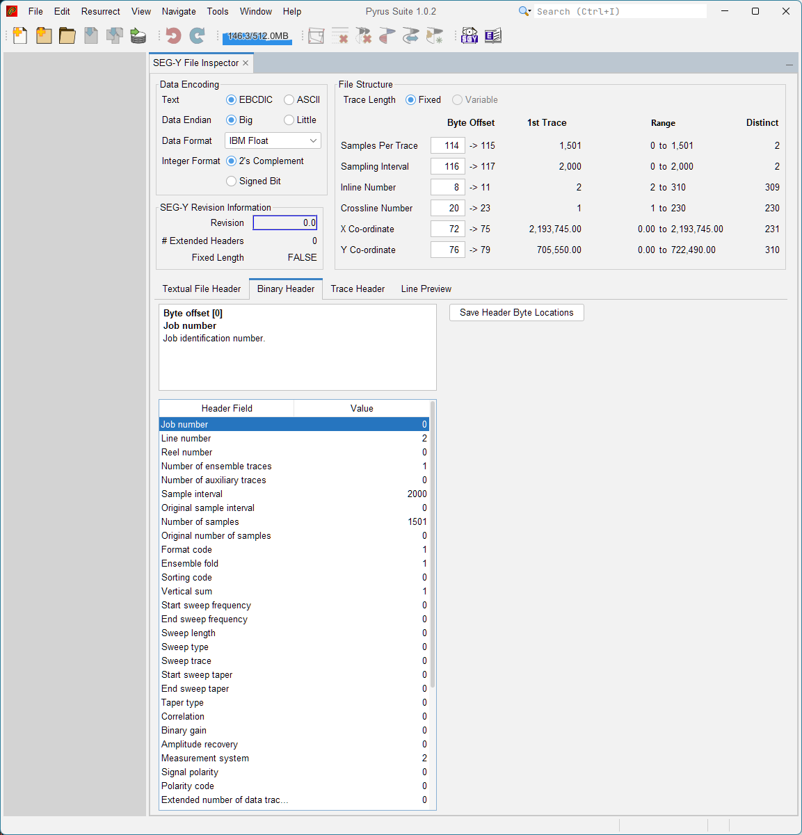
Pyrus displays these fields in a table. Selecting a table entry should show the definition of that field in accordance with the SEG-Y format published standard. For example the job number (byte offset = 0) is shown selected in Figure 3.
Correcting Byte Locations
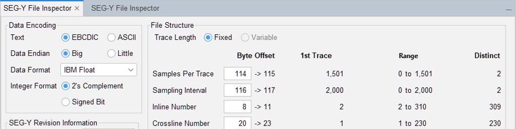
Some (all?) SEG‑Y files use non-standard byte locations for key trace header fields. Pyrus allows these byte locations to be updated directly from the inspector by typing the correct byte offsets into file structure fields in the top right of the panel. When the user edits the byte locations, the inspector will attempt to iterate over all the traces and show the range of values that was found across all traces in the file. For very large files this can take a while (where a while is measured in minutes, and depends largely on the input/output speed of the hardware on which the SEG-Y file is stored). Once all the trace headers have been indexed, the values shown for the header range should change to black.
Note that in the example below there are two distinct values for ‘ns’ (number of samples) and ‘dt’ (delta time, or sample interval in microseconds). Typically a good SEG-Y file with fixed length traces will have just one value for each of these parameters which is repeated in every trace header. For this example 3D Stratton SEG-Y file, there is a single trace with a dud header (all zeros). This can be seen as the number of distinct values is two, not one. Generally this isn’t something to worry about too much as a SEG-Y file imported into Pyrus will assume a fixed trace length – if there is a trace with a missing ‘ns’ or ‘dt’ value, the main values for the rest of the traces will be used.
Rather than having to enter the header byte locations for non-standard SEG-Y each and every time a SEG-Y file is opened, Pyrus has the capability to store these header byte locations in the binary header. The SEG-Y format has several undefined fields in the binary header, and these are used by Pyrus to store the trace header byte locations for the number of samples, sample interval, inline number, crossline numberm inline location and crossline location. The values currently set in the ‘File Structure’ panel group in the top right can be saved into these locations using the ‘Save Header Byte Locations’ button in the ‘Binary Header’ tab.
Trace Header Inspection
Each individual trace contains a 240-byte header followed by the trace data itself. The trace data comprises ‘ns’ samples, where the value ‘ns’ is defined in the trace header and should match the binary value for ‘ns’ if fixed length trace data is used. Each sample will have the same number of bytes per sample
The trace header contains per‑trace metadata such as:
- Inline number
- Crossline number
- CDP coordinates
- Number of samples
- Sample interval
- Elevation and offset information
Pyrus reads trace headers directly from the file and displays them in a table. This allows the correct trace header locations to be identified through inspection, and the trace header locations can be updated in the ‘File Structure’ panel group in the top right of the SEG-Y inspector panel. The actual data values are shown for the trace using a wiggle plot. By clicking and dragging a zoom window over the trace, it is possible to zoom in an see a particular time range of data. The wiggle plot uses shaded peaks for positive values, and unshaded lines in troughs for the negative values. An example of a trace and its data is shown in Figure 4.
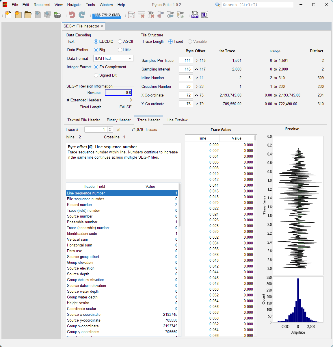
Note that editing of individual trace values is not currently possible, although this may change in future if there is a need to introduce the functionality. Each trace is accessed sequentially, starting with trace number one. The associated inline and crossline reference numbers are shown for each trace.
Geometry Overview
Opening the SEG-Y inspector, or changing the header byte locations in the ‘File Structure’ panel group in the top right of the SEG-Y inspector panel will initiate a search over all traces in the file. This is known as trace indexing. Each trace header is interrogated, and key values in that header are stored, along with the starting trace location in the file. This makes it quicker and easier to access data in a SEG-Y file as there is no guessing as to where each trace starts.
Previewing Seismic Data
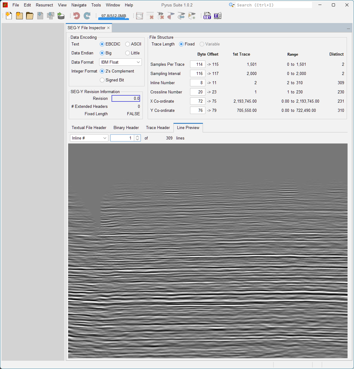
The inspector includes a lightweight seismic viewer that allows users to preview inlines and crosslines. This is accessed from the ‘Line Preview’ tab. Note that the correct trace header bytes must have been loaded, otherwise the line previous may not function correctly. The sequential inline or crossline numbers are accessed through selecting either ‘Inline #’ or ‘Crossline #’ following by the sequential number. The line is displayed using a greyscale variable density plot. It is possible to zoom into this image using the middle mouse wheel, and the object viewed can be panned by clicking and dragging on the image. An example of the preview line is shown in Figure 5.
Note that this is not intended to be a full seismic interpretation tool, and it is only intended too provide a quick way to visually confirm the seismic polarity, amplitudes, continuity and the overall correct settings for accurate importation of SEG-Y.
Manual QC Checklist
Because seismic QC is inherently visual, Pyrus does not attempt automated QC. Instead, users can scroll through slices and visually inspect the data. Although Pyrus does not perform automated quality control (QC), severai manual checks are recommended. These checks are made easier using the Pyrus SEG-Y inspector tool.
Header Checks
- Does the textual header look correct? Look at the textual header and check both EBCDIC and ASCII encodings. If the text does not appear garbled, high chances are that it is correct.
- Does the binary header contain sensible values? For post-stack data, the number of traces per ensemble should be zero, the number of samples, and samples per trace should be have been set.
- Are byte locations for NS, DT, ILINE, XLINE, CDPX, CDPY correct? The only real way to check this is iterate over the various trace headers in the file, and to check that values such as ‘ns’ and ‘dt’ are invariate for fixed length traces, but vary predictably for line numbers etc.
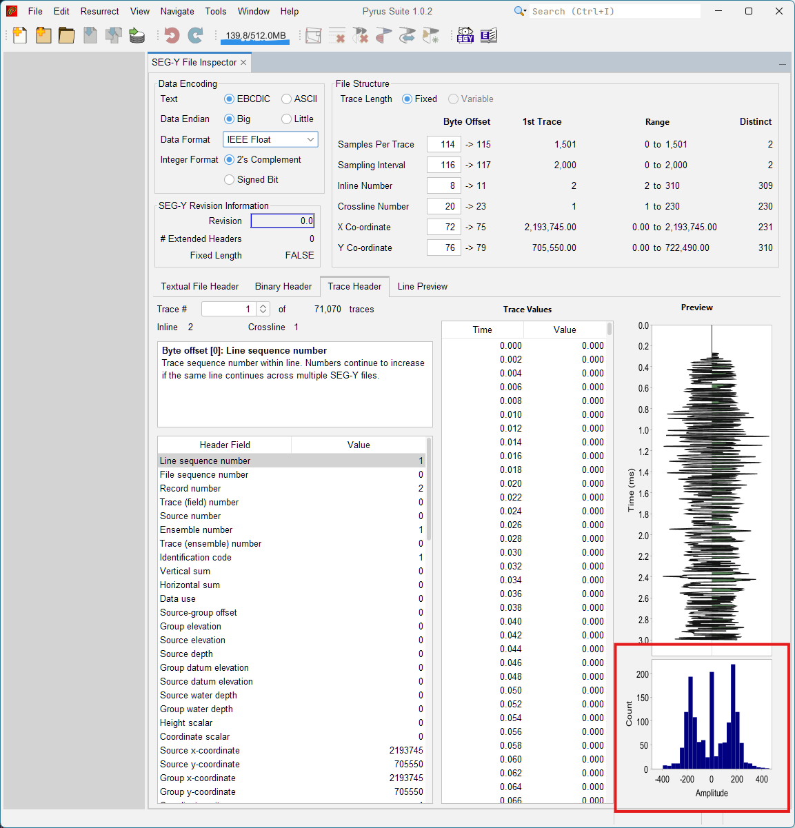
- Is the data format code valid (1–8)? Crucial that the data format code is known. The format code (byte offset 24) should be set to (1) or possible (5). Other values are possible, but IBM floating point format or IEEE floating point format are the two most common data formats encountered. If the wrong floating point format is used, the data might look mostly correct, but will subtly different. It is easy to spot this error by examing a histogram of values for each traces as shown in Figure 6. Incorrect floating point format will have multiple concentrations of values, but the correct data format should have a single peak around zero. Similar data format issues can be uncovered by looking at the data endianess.
Geometry Checks
- Do inline and crossline ranges match expectations? Inline and crossline reference numbers should increase monotonically and with equal interval spacing.
- Are coordinates scaled correctly? The co-ordinates may be scaled by another value – typically ‘scaleo’ stored in the co-ordinate scalar at byte offset 70. Here the value may be positive or negative, and should be in orders of 10. Values of less than 10 indicate to divide by the ‘scaleo’ variable, and positive values to multiply. If the trace header value shown does not look reasonble, it is worth remembering that the original specification called for a simple integer encoding with a sign-bit. Modern programs conveniently discard this, and record the trace scaling using two’s complement logic for negative numbers. Switching between original specification and two’s complement is an important step to ensure that all the monsters can be captred.
- Are trace counts consistent across lines? The number of traces in each inline (and crossline for that matter) should generally be equal for each line. If they are very inequal, it may be necessary to pad lines with zero data.
Data Checks
- Are there dead traces? This is currently hard to find, but by iterating over all the trace in the file, it may be possible to determine which traces are dead, and to then intelligently fill the dead trace from missing values.
- Is polarity consistent? Positive peaks should be consistent across the entire data sample. The line preview may prove useful to quickly see if there are polarity reversals.
- Are amplitudes reasonable? This is a key consideration. For seismic data, most values will be centered around zero, with +/− a fixed amplitude value. If the data format has been incorrectly applied, then the histogram of trace values will show multiple peaks (see Figure 6). Note that this multi-peaked histogram should not occur with seismic data when the correct data format it applied.
- Does the data appear continuous across lines? By checking on a few inlines and crosslines, it should be possible to determine, via inspection, whether there is a continuous trend for the data across sections.
Summary
The SEG‑Y Inspector Tool provides a fast, reliable way to examine SEG‑Y files before importing them into a Pyrus project. By reviewing textual headers, binary headers, trace headers, geometry, and preview lines, users can quickly identify inconsistencies or non‑standard formatting.
Once the file has been inspected and any necessary header corrections have been made, the next step is to import the SEG‑Y file into a new Pyrus project, which is covered in the companion article.